Wound Rotor Motor Wiring Diagram
A 4 pole 60 hertz motor runs at 1740 rpm rpm synchronous = 120 x 60 / 4 = 1800 rpm slip = ( 1800 ‐1740) / 1800 = 60 / 1800 =.033 = 3.3%. Wound rotor motors are also referred to as “slip ring motors.”.
Patent US5770909 Wound rotor synchronous and field control system therefor

These slip rings are attached to brushes and variable power resistor banks, where operators can change the speed of the motor by varying the resistance through the rotor coils.

Wound rotor motor wiring diagram. The basic construction of dc motors is relatively simple, and a simplified circuit diagram is shown in figure 1: Shunt wound dc motor wiring diagram wiring diagram is a simplified standard pictorial representation of an electrical circuit it shows the components of the circuit as simplified shapes and the facility and signal contacts together with the devices. Their sole purpose is to allow resistance to be placed in series with the rotor windings while starting (figure below).
Rotor electrical frequency = slip x stator frequency at synchronous speed slip = 0, rotor frequency = 0, (no frequency, no induction) at stall slip =1, rotor frequency = line frequency for our example above rotor. The rotor consists of a rotor core a rotor winding and a rotating shaft. Dc shunt motor construction circuit diagram and its applications.
A induction motor with a cage rotor b the squirrel cage winding. The rotor core is also part of the main magnetic circuit generally by the thickness of 05mm silicon steel stack the core fixed in the shaft or rotor bracket. Slip ring motor starter diagram pdf.
It is provided with a field winding on the stator which is connected in series with a commutating winding on the rotor. Basic circuit diagram of dc motors. An electric generator is mechanically identical to an electric motor, but operates.
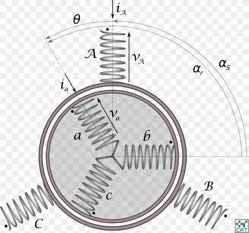
It is composed of two vital components, the stator and rotor, which interact electrically and magnetically to produce rotational motion on an output shaft. A wound rotor induction motor has a stator like a squirrel cage induction motor, but a rotor with insulated windings brought out via slip rings and brushes. Rotation of the stator magnetic field is equivalent to moving the wire in a stationary field.
Adjusting the resistance allows control of the speed/torque characteristic of the motor. Motor wiring diagram d c. 3 phase induction motor control using variable frequency drive vfd elex focus electrical circuit diagram circuit components circuit diagram slip is defined as the difference between the flux speed and the rotor speed.
The below figure shows the wound rotor induction motor diagram. An electric motor is an electrical machine that converts electrical energy into mechanical energy.most electric motors operate through the interaction between the motor's magnetic field and electric current in a wire winding to generate force in the form of torque applied on the motor's shaft. The dc shunt motor construction is the same as any type of dc motor this motor can be constructed with the basic parts like field windings stator a commutator and an armature rotor.
Most wound rotor motor rotor circuits use In contrast, a traditional induction motor (aka “squirrel cage motor”) has windings that. The original wiring diagram showed the proper arrangement of windings to create a larger wye system in which there are four equal windings between any two leads.
The block diagram of the. The loop ends are fixed to the slip rings, and two brushes make the connection between the slip rings and the external circuit. A universal electric motor is designed to operate on either alternating current or direct current (ac/dc).
In this wiring setup, there are 4 windings in series between any two line leads. What makes the wound rotor motor a unique induction machine is its rotor. Instead of a series of rotor bars, a set of insulated rotor coils is used to accept external impedances.
However, no power is applied to the slip rings. This rheostat resistance is gradually cut out as the speed of the motor increases. This diagram is purposefully vague as to where the stator field is.
They are used in large pumps in water industry. It is a series wound motor. In wound rotor motors, the rotor is “wound” with wire similar to the stator, with their terminal ends connected to 3 slip rings on the output shaft.
Shunt wound dc motor wiring diagram wiring diagram is a simplified standard pictorial representation of an electrical circuit it shows the components of. Wound rotor induction motor is used in applications which require smooth start and adjustable speed. Some of the applications of this motor include cranes, mills, hoists and conveyors.
Figure 1 one loop of rotor winding connected to outside circuit through slip rings. Typical wiring diagram for drum controller operation of a.c. An interruption of the rotor circuit can result in a voltage transient (e.g., “rapid restrike” or “reclosure”) failure mode.
Drawing the schematic diagram of autotransformer starter, dol starter and st. Wound rotor induction motor is also used in fans, blowers and mixers. When a wound rotor motor fails, there are several things to check to determine the underlying root cause of the failure.
Although the motors and connections look similar on the outside, this article discusses the internal construction for delta wound motors.
Automatic Acceleration for Wound Rotor Motors

Why do we need a starter for a threephase induction motor? Quora
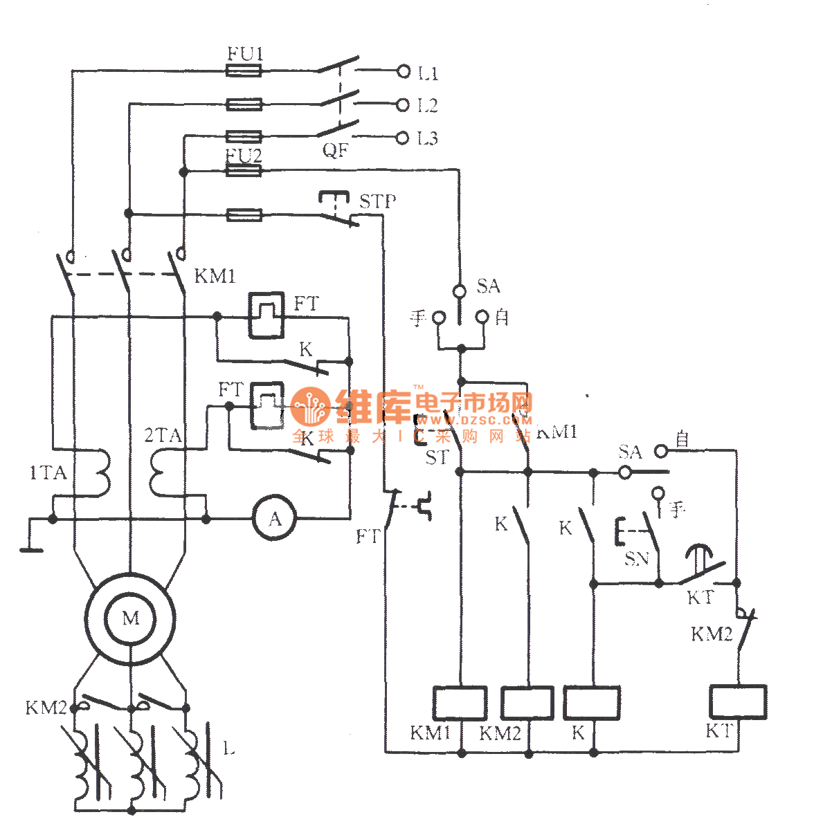
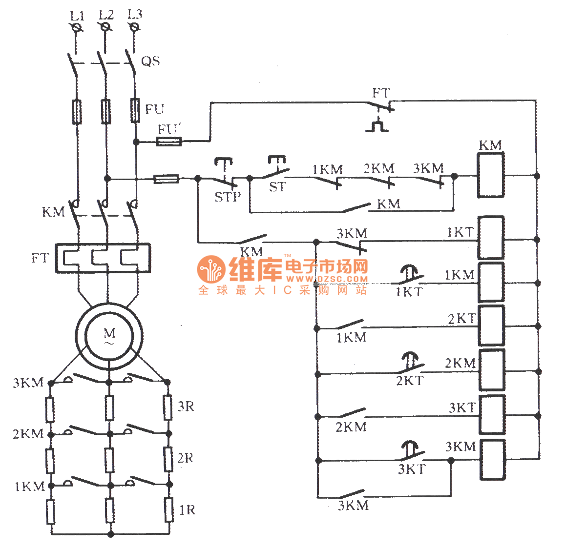
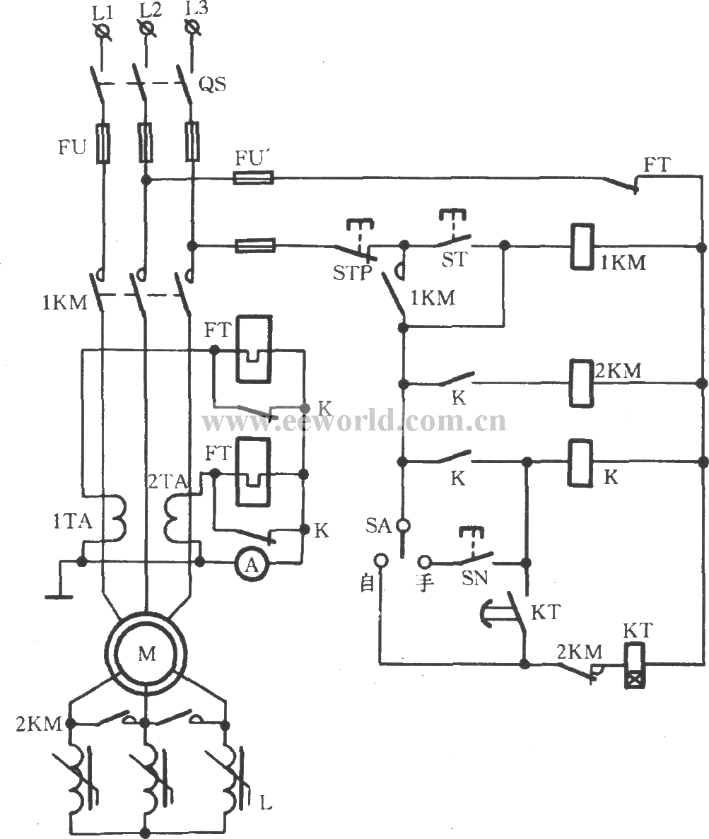
Wound rotor induction motor manual and automatic serial reactor stepdown startup circuit
Induction Generator Wiring Diagram
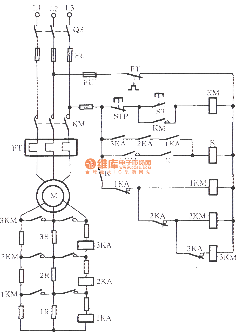
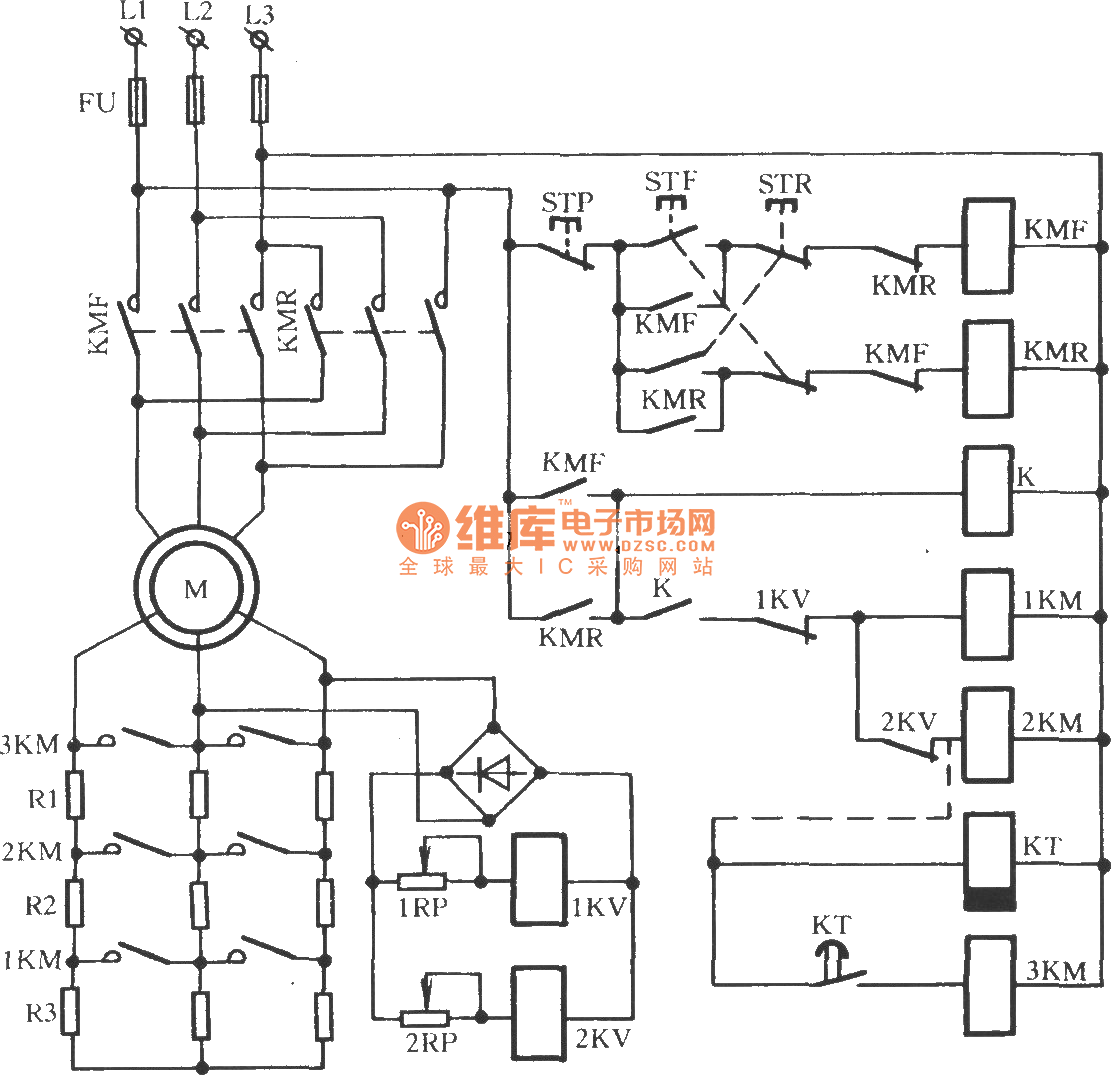
Wound rotor induction motor serial resistor stepdown startup circuit Relay_Control Control
wound rotor motor starter motorcyclepict.co
Slip Ring Rotor Or Wound Rotor In Three Phase Induction Motor Electrical engineering int

Classification of Electric Motors Part Three Electrical Knowhow

wound rotor induction motor serial reactor stepdown starting circuit Relay_Control Control
Wound rotor type motor reverse brake circuit Relay_Control Control_Circuit Circuit Diagram
Synchronous Motor Induction Motor Wound Rotor Motor Electric Motor, PNG, 1610x1504px
Wound Rotor Motor Circuits Electronics Knowledge Pinterest Motors

Typical Starter Wiring Diagram Nice Typical Wiring Diagram, Drum Controller Operation Of A.C
AC Dynamic Lowering Hoist Control ECN Electrical Forums
Guide to the Power Circuit and Control Circuit of the Wound Rotor AC Induction Motor

Engineering Photos,Videos and Articels (Engineering Search Engine) CHAPTER 2 PRINCIPLES OF

Typical wire diagram of drum control AC wound rotor motor Schematic drawing, Diagram, Segmentation

Guide to the Power Circuit and Control Circuit of the Wound Rotor AC Induction Motor

☑ Define Wound Rotor Induction Motor
